Dynamic Point Lighting - An OpenGL Tutorial from basic principles.
- Andrew Watts
- Oct 1, 2015
- 9 min read
PreExisting Knowledge Required:
Render Targets & OpenGL Shaders.
The Concept.
The idea of a dynamic light is one which you can move around your scene and adjusts the shaddows it casts accordingly. The proccess is costly to exicute but it does have a very nice effect.
The reason it is costly is we have to render the scene from the lights point of view.
take for example this image.

From the camera's perspective, we have a pixel being formed from the Green Shape at the end of the blue line. We can sample the texture of this object, but what we want to know is , is it in the shaddow of the point light or is it not?
By passing in the location of the point light we can get a result for how far the pixel is from the light. A Distance messurment as such. I have shown this above as a red line. this line can determin the intensity of the light at that point, but not if it has been blocked by a shaddow.
Its easy to check the distance from the camera to the pixel, by checking the camera point to the pixels point, we could know how far the pixel is from the camera as shown in blue.
In a similar way, if we rendered the scene from the lights perspective much like in the case of the blue line, we could work out the distance to the yellow line, describing to us how far the back side of that green object is from the light.
By comparing the distance of the Red and yellow lines, we can see that the pixel of intrest is indeed in the shaddow of the point light because the light beam only travels the yellow distance, and not the red distance that is needed to illuminate our pixel at the end of the blue line.
This is the basic mechanic of Dynamic Lighting, it requires us to render the scene from the lights perspective.
Complications
When rendering a scene, we genrally only look in one direction, Foward. thats easy, The problemb is, if im going to render the scene from the lights perspective, what direction is it looking?
you may just think, oh ill point the camera at the light toward the player, but will that work? look for example at a light in a room
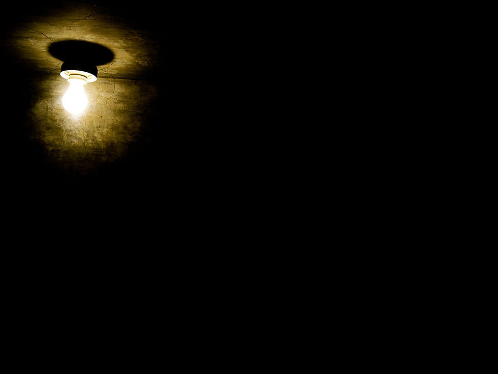
if a camera from the lights perspective was looking toward us, we would be able to sample the pixels in the for ground of the light, but not in the background of the light because the camera isn't looking that direction.
It becomes pritty evident, we need the lights camera to render the scene in every direction, because the point light casts rays in every direction.
Implementation - CubeMapping
The solution is somthing called a cube map.
Imagion for a secound I take a camera and set it up with an aspect ratio of 1 to 1, so its render is as high as it is wide, This is a cube. Then imagion I set the field of view such that the camera spans a 90 degree radius infront of it.
if we took 4 of these cameras and pointed them in the X possitive, X Negitive, Y Possitive and Y Negative dirrections then the edges of each cameras field of view match perfectly for a full 360 degree view, then by adding 2 more cameras pointing in the Z possitive and Z Negative directions. we could end up with a cube shape of cameras that manage to capture everything around the point.
The Camera set up would look as follows, with each piramid being its own camera.
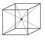
In order to get this set up the camera's
Field of view will need to be set as
glm::pi<float>()*0.5f in OpenGL
the Aspect ratio will need to be
1.
you should be able to use the GLM lookat function to generate the camera's direction. use its location as the light position, and then add a unit vector to the lights position for each of the dimensional directions.
ie.
LightPos + vec3(1,0,0) //(Xpositive)
LightPos - vec3(1,0,0) //(XNegitive)
LightPos + vec3(0,1,0) //(Ypositive)
LightPos - vec3(0,1,0) //(YNegitive)
LightPos + vec3(0,0,1) //(Zpositive)
LightPos - vec3(0,0,1) //(ZNegitive)
for X and Z use the camera's up direction to vec3(0, 1, 0);
and for the Y camera set it to vec3(1, 0, 0) for the Ypositive direction.
and set it to vec3(-1, 0, 0) for the Ynegitive direction.
Now all we need is to have the faces of that cube being render targets in open GL, for each face we can render each respective camera output to the target. For debugging purposes we often unrap this cube much like the cardboard box bellow. For this Tutorial we will be using 6 render targets, but OpenGL also has support for a CubeMap as standard. We are ussing 6 Render Targets to help get accross the concept of what is happening and how to right the code to access a cube map yourself.
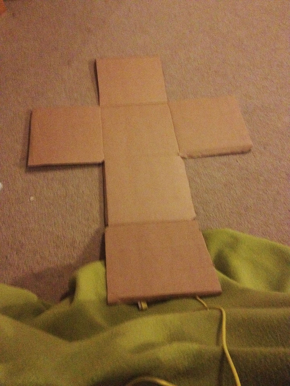
you can use a vertex and fragment shadder to easily print these result to the screen without the 3D perspective.
for example set up some shadders like these to print a simple texture to the screen, hence you can choose to print your render targets to the screen to see the result.
Vertex
#version 410 layout(location = 0) in vec4 Position; layout(location = 1) in vec2 TexCoord; out vec2 vTexCoord; void main() { vTexCoord = TexCoord; gl_Position = Position; };
Fragment
#version 410 in vec2 vTexCoord; out vec4 FragColor; uniform sampler2D diffuse; void main() { FragColor = texture(diffuse,vTexCoord); };
The next question is, what am i rendering from that lights perspective? I dont need to look at the game world in full colour because we arn't going to need that information, its just the distance to the camera we need to know. as of such our render targets only need to be grayscale and store one value per pixel.
as of such we just need to use a shader for our geometry at this point that is short and sweet.
Take for example this Fragment shader code I wrote for mine.
#version 410 in vec3 vPosition;
out vec4 FragColor; uniform vec3 LightPos; uniform float LightRadius;
void main() { float D = length(LightPos-vPosition); //Depth FragColor = vec4(1-D/LightRadius,1-D/LightRadius,1-D/LightRadius,1); //Results };
you can see I set a distance, and then divide it by the light radius, this produces a number between 0 and 1 for all the times that the result is within the lights radius, where 1 is when the light is totally black and 0 for when the light is totally bright.
because this is a bit back to front i did the final equation as 1-D/LightRadius so that the result is 0 for black and 1 for full, negitive for no effect.
By ussing that simple code and the cube map camera setup with your render targets you should be able to generate images somthing like this in your openGL game scene.

print each of the render targets to your screen and arrange them so you get the flattened cube layout as shown above, each of the edges should match up. for exmaple, you can see that at the top their is two buildings on the left hand edge, that match at a 90deg angle the edge next to it, you can see if it was folded up into a cube how the entire scene is captured. (the above image is slightly streatched in width), each segment should idealy be a cube not a rectangle (as i had it printed *sorry*) to visualise it easier.
Implementation - Shadding
Once we have our cube map, lets move on to how we might read one using our own implementation.
Firstly, lets agree apon some names for our 6 render targets.
Mine were set in my shadder as
uniform sampler2D XP; uniform sampler2D XN; uniform sampler2D YP; uniform sampler2D YN; uniform sampler2D ZP; uniform sampler2D ZN;
The first letter stood for the dimension in which the camera faced, and the secound for if it was the possitive of negitive direction.
for my implementation I was going for a bump mapped result, so my other inputs were
//Inputs in vec2 vTexCoord; in vec3 vNormal; in vec3 vTangent; in vec3 vBiTangent; in vec3 vPosition;
corrisponding to the vertex data I was getting from the Vertex Shadder.
//Uniforms uniform vec3 LightPos; uniform vec3 LightColour; uniform vec3 CameraPos; uniform float SpecPower; uniform float SpecIntensity; uniform float Brightness;
uniform sampler2D diffuse; uniform sampler2D normal;
uniform float LightRadius;
The following should be pritty straight foward
My output value was simply the following in this fragment shadder.
//Outputs out vec4 FragColor;
So lets get down to it,
When it comes to light intensity at the fragment we are interested in, it comes down to 2 things.
Brightness un-Obstructed (collisions ignored). = Brightness*max(1-d/LightRadius,0);
where d = length(LightPos-vPosition);
to explan this in words, what we are saying is check how far out from the light we are compared to its radius, and generate a number between 0 and 1 for this value where 0 is no light and 1 is full light brightness. then multiply this by the lights brightness.
Brightness Obstructed (collisions considered)= gotten from the cubeMap how bright was it when the light hit the wall from the lights perspective toward the fragment.
if the obstructed brightness is closs enough to the un-obstructed brightness, then we are good to proceed with inplementing the un-obstructed brightness as the fragments brightness, since we can assume the fragment is not obstructed (hence not in shaddow)
however if not, we should return 0 for the brightness because it is not getting any light from the point light as it is obstructed.
the interesting question is, how do i know which render target to access the Brightness Obstructed Value from and what is the reading proccess.
Lets have a look at a diagram that might help.
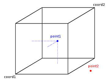
lets say point 1 is the light at the center of the cube map and point 2 is our fragment,
what we need to do is work out through which of the faces the line connecting point 1 and point 2 will pass.
The conclusion I came to was that if we know which of the dimisions the direction vector has the largest value in, it will pass though that dimensions face first in a unit cube, since it will travel in that dimensions direction the most as it moves out from the center.
as of such I based my Fragment shader code for the shaddowing of my textures as follows.
float Intensity() { float d = length(LightPos-vPosition); float v = max(1-d/LightRadius,0); //expected value if(v==0) { return 0; } else { vec3 DeltaN = normalize(vPosition-LightPos); //Direction vector vec3 DeltaNA = abs(DeltaN); //AbsoluteValue of that vector. float Max = max(DeltaNA.x,max(DeltaNA.y,DeltaNA.z)); //what is the largest X,Y,Z value
vec3 MultDelt = (DeltaN/Max); //make the Direction vector touch the side of the CubeMap by making atleast one of the dimensions values equal 1. float AdjustmentForRasterInacuracy = 0.01f;
float ref = v+AdjustmentForRasterInacuracy ; //what we will check against, expected value plus a small value of 0.01f is added else half of the values will return a shaddow because we are sampling a cubemap which is raster not dynamic.
if(DeltaNA.x == Max) //ask if x was the largest dimension { vec2 Access = vec2(MultDelt.z,MultDelt.y); //find the texture access point.
if(DeltaN.x > 0) //ask if it is the possitive or negitive x dimension side. {
if(ref>texture(XP,Access/2 + vec2(0.5f)).x) //find the value on the cubemap and compare if it is less then the refrence value we expected. return Brightness*v; //return lit brightness value else return 0; //return a shaddow solution for brightness } else { Access.x = -Access.x; if(ref>texture(XN,Access/2 + vec2(0.5f)).x) return Brightness*v; else return 0; } } else if(DeltaNA.z == Max) { vec2 Access = vec2(-MultDelt.x,MultDelt.y); if(DeltaN.z > 0) { if(ref>texture(ZP,Access/2+vec2(0.5f)).x) return Brightness*v; else return 0; } else { Access.x =-Access.x; if(ref>texture(ZN,Access/2+vec2(0.5f)).x) return Brightness*v; else return 0 } } else { vec2 Access = vec2(-MultDelt.z,MultDelt.x); if(DeltaN.y > 0) { if(ref>texture(YP,Access/2 +vec2(0.5f)).x) return Brightness*v; else return 0; } else { Access.y = -Access.y; if(ref>texture(YN,Access/2 + vec2(0.5f)).x) return Brightness*v; else return 0; } } } }
from here we have the lights brightness at the given fragments location. If we use that in conjunction with the surface normal, we should get results that look like this in your scene

now we just need to multiply our standard shaders colour value by this brigtness and we have a solution for a single point light that is dynamic!
see bellow my code example for a bump mapped texture.
vec3 GetNormal() { mat3 TBN = mat3(normalize(vTangent),normalize(vBiTangent),normalize(vNormal)); vec3 N = texture(normal,vTexCoord).xyz *2-1; return normalize(TBN*N); }
float Spec(vec3 Norm) { vec3 E = normalize(CameraPos-vPosition.xyz); vec3 R = reflect(-normalize(LightPos-vPosition.xyz),Norm); float s = max(0,dot(E,R)*Intensity()); return pow(s,SpecPower); }
void main() { vec3 Normal = GetNormal(); float D = max(0,dot(Normal,normalize(LightPos-vPosition.xyz))); float spe = SpecIntensity*Spec(Normal); vec3 TexCol = texture(diffuse,vTexCoord).xyz; vec3 Col = Intensity()*(D*TexCol+spe*TexCol)*LightColour; FragColor = vec4(Col,1); };
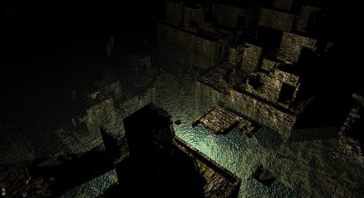
The final result I had in my project looked as follows.
Further Work Options
My Ideas to progress this further is to
1. rewrite a solution using the openGL's cubemap rendertarget for a faster implementation, also allowing for more total light inputs, which leads to my next one.
1.5 Find a better solution to reduce error from the rastor cube map if OpenGL implementation doesnt solve it.
2. write the code such as to take in a group of pointlights, not just 1.
3. write the code for multiple light shapes such as a flurresent light (line between 2 points), a sphere, a cube and a capsual.


Comments