3D Voronoi Fracturing - How To Split An Object With Maths.
- Andrew Watts
- Oct 2, 2015
- 14 min read
In the game world, Every now and then you may want to split a space up using mathamatics, This Blog Entry is a tutorial to help you understand how the mathamatics behind a first principle Voronoi fracturing code set might work. Bellow for example you can see a collomn being split into many random chunks via the process we are going to investigate. I've removed random chunks to show the effect more prominently.

Also Attached is the same effect used on a building to give an aged look, here a voronoi fracture allowed me to take out a section of the wall of these two


The above two shapes were created compleatly from code in my own Rendering Engine.
Its important to note this solution is not the quickest but rather a first principle solution to the equation, and is best used as an offline process for when large numbers of fractures is needed and an online process for fractures with less then 20-30 parts from this tutorial. that said this proccess can be optimised alot further then is presented in the tutorial if you so wish to spend the time. So what is Voronoi Mathamatics?
The principle is Simple, you have a Mathamatical space and you want to split it into 'N' number of chunks.
to do this we first place 'N' number of points in the Space. lets call them sites, and the principle is - that around these sites we want to define a cell such that any time you are within that cell, the site at its center is closer then any other site in the space. the end result in 2D would look as follows.

Getting Started..
1.Define the Space.
This could be the real number space in 3 dimensions from -Infinity to +infinity in X,Y and Z or it could be defined by you.
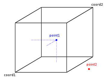
For example, 0 to 1 in X,Y and Z dimensions. shown bellow.
Start by Creating a class that defines the space.
it will simply will need two Vector3 variables to store the min and max values in all 3 dimensions that a site could take.
lets say it looks somthing like this.
class VoronoiBoxContainer { public: VoronoiBoxContainer(vec3 Min, vec3 Max); ~VoronoiBoxContainer();
vec3 Min; vec3 Max; };
In the bellow diagram vec3 Min would take on the coord1 position, and vec3 Max would take on the coord2 position, the key thing is that in a voronoi space, you can see point1 is a valid point within the space, but point

This takes us to our next Step.
2. Fill the space with Sites.
Next lets look at the sites we want, we could place these ourselves, but lets start by making a function that just adds a number of sites to random locations within the container.
to do this we are going to need a Site Class aswell as a Cell Class Every site will have its own surrounding Cell, so set up the cell to inherate from Site.
class VoronoiSite { public: VoronoiSeed(vec3 _loc); vec3 Location; };
class VoronoiCell:public VoronoiSite { public: VoronoiCell(vec3 Location); ~VoronoiCell();
};
Next modify your container to be able to hold VoronoiCell's in a vector and add a function to add random sites.
float Random01() { return (float)rand() / RAND_MAX; }
void VoronoiBoxContainer::AddRandomSite() { float XRange = Max.x - Min.x; float YRange = Max.y - Min.y; float ZRange = Max.z - Min.z;
vec3 Loc = vec3(Min.x + XRange*Random01(), Min.y + YRange*Random01(), Min.z + ZRange*Random01()); VoronoiCell* NewCell = new VoronoiCell(Loc); Cells.push_back(NewCell); }
prehaps you might also want to add
void VoronoiBoxContainer::AddRandomSites(int Number).
Ill leave you to work out that implementation with a simple for loop (if you don't know how to do that, I suggest an easier tutorial, Its about to get tricky real soon :P)
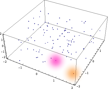
If we were to visualise what we have now, it should be somthinging like this for a -2 to 2 container. with a decent Number of sites spawned in it.

3. Create Needed Mathamatical Functions
You can do this yourself like i did for a challange, or im sure you can find these equations online as this is very basic carteesian mathamatics that has been needed for centuries, the needed classes are.
3D Line Class
- this line needs to be defined by a point in 3D space and a vector that points along the line.
-This line needs a function to find the point of contact with a 3D Plane aswell as the vector multiple above that finds the solution point.
-This line needs a function to find the point of contact with another 3D line on the same 3D plane.
3D Plane Class.
-Defined by a point in 3D space and a normal from its surface.
-this Plane needs to have a function to find the 3D line that defines the points of contact with another 3D plane.
-this Plane needs to have a funtion to find out if a point is above or bellow the plane based on the planes surface normal.
you should end up with some functions that look like this (again this is common maths and should be common enough for you to easily find the implementation online.
class Line_3D //Infinite length; { public: Line_3D(); Line_3D(vec3 _PointOnLine, vec3 _Direction);
vec3 ClossestPointTo(Line_3D Other); vec3 Intercept(Line_3D OtherLine); //Lines must sit on same plane float GetTValue(vec3 Point); //Point Must be on same Line; (T is the multiple of the _Direction vector from the _PointOnLine that equates to the point. vec3 GetPointFromT(float T);
vec3 PointOnLine; vec3 Direction; };
class Plane_3D //Infinite bounds { public: Plane_3D(); Plane_3D(vec3 _PointOnPlane, vec3 _Normal);
bool IsPointUnder(vec3 Point); // bellow when not on the same side as the normal vector. Line_3D GetInterceptLine(Plane_3D OtherPlane); // returns the line in 3d of that describes where two planes intercept, returns a line with constructor Line3D(vec3(0),vec3(0)) if the planes are parrallel.
float GetIntercept(Line_3D Line); //float is the Line Normal Multiple that gets to the intersection from point on line.
vec3 PointOnPlane; //(x0,y0,z0) vec3 Normal; //(a,b,c)
//a(x-x0) + b(y-y0)+c(z-z0) = 0 //ax+by+cz +d = 0 where d = -(ax0+by0+cz0) float d;
};
Even though the implementation is common, its imperitive you understand how these functions behave in 3D space.
Start by getting a peice of paper or card. think of this a a plane in 3D space.
Next get a courner of the card and fold it such that one courner meets its oppisite courner and then open it up a bit you have just created a plane plane interseption where the crease is the resulting 3d Line.
I strongly suggest you build one of these to help you visualise the future steps.

Likewise If i add a third plane , we get more intercept lines ASWELL as a common Intercept Point from those lines

Its important to note that when the surface normal of two planes is equal or opposite (ie normal1 = -normal2) their is no intercepting 3D line.
Also In order for two 3D lines to intercept at a point, they must share a common plane, they also must not have equal or opposite directions (ie direction1 = -direction2);
test this on your card so you are sure you understand why, as we are going to need to remember that when we later form a sites surrounding cell.
4. Finding Bounds between one site and another to form Cell walls.
Lets say we want to compute the surrounding Cell of the site highlighted in pink bellow.

By first principles, the cell is the space that defines being closser to this point then any other in the container.
Lets say now the point in orange is the only other point in the contianer for now.

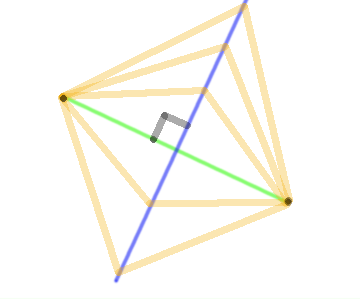
By Deffinition their is only two cells in the container, the common wall that would split the container into these two cells is pritty easy to find. to do this, consider the green line between these two points and the blue cross marking its center. that blue cross is on the boundary between the cells.

This blue cross is as easy to find as writing some code that says
BlueCross_Location = (PinkPoint + OrangePoint)/2;
Likewise the green line can be defined by two things (a point on the line, and the direction of the line). currently we have 3 points on the line (PinkPoint, OrangePoint and the blue cross) the direction is also easy to find with code.
GreenLine Direction = Normalize(PinkPoint - OrangePoint);
(use these two functions to help define void VoronoiCell::GenFaceFromSeed(VoronoiSeed Seed); further down the page)
The reason this is of intrest to us is because if we know a point on the boundary wall and the direction of the boundary wall, we then know the equaiton of the boundary.
we can visualize this as shown bellow by the blue box, this is where the blue cross is a point on the plain, and the green line direction indicates the surface normal.

If you need to understand why this is the boundary, check out the bellow image, showing this from the top view, here we can see when we make a plane with the blue cross point and the green surface normal, the resulting plane has equal distances from any point on the plane back to the two forming points shown as black dots. hence this obays the principle of voronoi fracturing such that going one side or the other of that blue plane will make the point closer to that sides site then the other.

Create a class to store this face/boundary result in, we need a class because we will need to evaluate more about these faces later in the proccess.
class VoronoiFace { public: VoronoiFace(vec3 Point, vec3 Normal); Plane_3D Plane; };
then add a vector of VoronoiFace's to the VoronoiCell Class so we can store any Faces we Generate.
std::vector<VoronoiFace> Faces;
Also add a vector of VoronoiPlanes that formed those faces to the VoronoiCell Class. I will explain later why this helps.
std::vector<Plane_3D> Planes;
Finally implement the following function from the above logic such that it creates and forms a Face and stores it in the Faces vector, aswell as storing the forming plane in the Planes vector.
void VoronoiCell::GenFaceFromSite(VoronoiSite OtherSite)
If you want an Extra Challange, have a think how you might scale the cells sizes based on a lerp function rather then an average function (center of two points) if you want more variance and control over your fracturing function.
5. Check Multiple Boundaries Around the site.
go into your Container class and add the following/similar function (you can choose to use pointers or choose not to, I would advise pointers as you can then keep a track easier of what the other forming site was if you need that information later on, for example, who does our current site share a boundary with.
void VoronoiBoxContainer::CalculateAllSites() { for (int i = 0; i<Cells.size();++i) { for (int j = 0; j < Cells.size();++j) { if (Cells[i] != Cells[j]) { Cells[i]->GenFaceFromSite(Cells[j]); } } } } }
Now remember back when we had our peice of card, when we had a flat peice and folded it, we formed a line that was the intercept of two planes. as we added more planes, we found each plane could have multiple edges/line intecepts. and those intercepts would start cutting into each other to shorten the lines..

Lets add a class to express these Intecept lines and how they shorten as more planes are added to form out voronoi cell bounderies.
class VoronoiEdge { public: VoronoiEdge(Plane_3D Plane, Plane_3D Other); VoronoiEdge(int PlaneID, int OtherID, Plane_3D Plane, Plane_3D Other);
Line_3D Line; glm::vec3 UpperPoint; glm::vec3 LowerPoint; float UpperT; float LowerT; bool Valid;
int ThisPlaneID; //position of plane in Planes Vector of VoronoiCell. alternitivly you could use a pointer int OtherPlaneID; //position of plane in Planes Vector of VoronoiCell. alternitivly you could use a pointer
bool CheckPlane(Plane_3D Plane); //returns true if still valid };
this class should store all the information regarding the intercept of two planes.
In the constructor we need to use the two input planes to generate the Line Variable using the mathamatical functions we set up earlier in the tutorial.
Check Plane is used when another plane is added/face is generated, and we are going to need to check if this new plane also cuts into this line and where. much line how plane 3 above put a limit on the first Intercept line shown by cutting into it, it put a boundary on the lines extent.
this is the purpose of the upper point and lower point variables, (these have respective T values that form them, see the Math variable section of this tutoria) the T values of these points initualy will be set to possitive infinity and negitive infinity respectivly. as the line is infinite in both directions, then as we Call CheckPlane, we see if the new plane has cut the line, and where.
we can use the line direction vector as a dot product with the planes surface normal to see if the upper point or lower point needs to be checked, and then we see if this value is lower then the existing value for upper point, or higher then the existing value for lower point. if the upper point is ever lower in T value then the Lower point, we know the line has been completly cut out of being a forming edge of the voronoi cell and the function should return false.
this was my implementaiton of that written logic.
bool VoronoiEdge::CheckPlane(Plane_3D Plane) { float Dot = glm::dot(Plane.Normal, Line.Direction); if (Dot > 0) { float T = Plane.GetIntercept(Line); if (T < UpperT) { UpperT = T; UpperPoint = Line.PointOnLine + Line.Direction*UpperT; } } if (Dot < 0) { float T = Plane.GetIntercept(Line); if (T > LowerT) { LowerT = T; LowerPoint = Line.PointOnLine + Line.Direction*LowerT; } } if (Dot == 0) { //if (!Plane.IsPointUnder(Line.PointOnLine)) // Valid = false; }
if (LowerT >= UpperT) Valid = false;
return Valid; }
Next lets go back to our old Form Face Function and make it look like this
void VoronoiCell::GenFaceFromSite(VoronoiSite* SiteRef) {
vec3 Direction = SiteRef->Location - Location; vec3 Pos = (SiteRef->Location - Location)/2;
vec3 Normal = Normalize(Direction); Plane_3D NewPlane = Plane_3D(Pos, Normal);
//Extra logic can be added here to make a plane cut that doesnt need to be based off another site. Plane_3D FinalPlane = Plane_3D(Pos, Normal); int FaceLoc = Faces.size(); int PlaneLoc = Planes.size(); VoronoiFace NewFace = VoronoiFace(Pos, Normal, PlaneLoc); NewFace.FormingOther = (VoronoiCell*)SiteRef; Faces.push_back(NewFace); Planes.push_back(FinalPlane);
CaclulateNewFace(); for (int Face = 0; Face <FaceLoc; ++Face) { RecalculateOldFace(Face,PlaneLoc); }
//Bellow is just to increase speed by culling faces that have all edges been made valid = false, from a new planes introduction, cusing the current face to be cut off completely from the convex hull of the cell.
for (int Face = 1; Face < Faces.size(); ++Face) //the first face gets culled unnecisarily since it has no forming edge to start with, and sometimes later. { if (Faces[Face].Edges.size() <= 0) { Faces.erase(Faces.begin() + Face); //RemoveFace(Face); --Face; }
} }
The purpose of the above is to define the face, check it against existing faces for any edge intercepts and then add it to the list of faces and planes with the functions CalculateNewFace(), and then check the effect on existing faces with Re-CalculateOldFace Function.
ill cover these two functions bellow.
6. Setting up a New Voronoi Face.
Lets go through the logic of setting up a Face for the first time. this means we have looked at a site somewhere in the container and we want to check the boundary between this site and the other.
When the new face is created, we need to know what other faces it is going to intercept, for this we check against all planes that have ever been considered by the voronoi cell in the past. these can be found in the Planes vector of the Voronoi cell class.
for each plane we generate a Voronoi edge and store it in the Edges vector of this face. so we have every possible edge that could be on this face. (this is the first for loop)
Next we go through every edge and check it against every other edge on the face via the forming planes other then this one to see if we have cut the line/edge any shorter then it currently is or if it has been cut off completely such that it nolonger exists. (this is the secound nested for loops segment)
Lastely we go through each edge and find which ones have veen set to be valid = false from the above loop and remove them from being considered any longer for the face.
void VoronoiCell::CaclulateNewFace() { int Face = Faces.size() - 1; int NewPlane = Planes.size() - 1; int NewFace = Faces.size() - 1; for (int Plane = 0; Plane < NewPlane; ++Plane) { VoronoiEdge NewEdge = VoronoiEdge(NewPlane,Plane,Planes[NewPlane], Planes[Plane]); Faces[NewFace].Edges.push_back(NewEdge); } for (int Edge = 0; Edge < Faces[NewFace].Edges.size(); ++Edge) { for (int Edge2 = 0; Edge2 < Faces[NewFace].Edges.size(); ++Edge2) { if (Edge != Edge2 && Faces[NewFace].Edges[Edge].OtherPlaneID != Edge2) { Faces[NewFace].Edges[Edge].CheckPlane(Planes[Edge2]); } } } for (int Edge = 0; Edge < Faces[NewFace].Edges.size(); ++Edge) { if (!Faces[NewFace].Edges[Edge].Valid) { Faces[NewFace].Edges.erase(Faces[NewFace].Edges.begin() + Edge); --Edge; } } }
7. Recalculating old faces when we add a new face.

This proccess is much like a block of butter, each time we check a face we are cutting off a nob from the block. any existing edges on that nob are thown out with it, and all we are left with is the central butter peice each time we cut through it with our knife. (the mathamatical forming faces) in this analogy, the butter peice is the container space and the knife is our planer bounderies between sites. for each site we start again with our butter peice and carve out the boundaries of the convex hull of that site by forming faces with each site in the container.
This is highly important as each time a new face is added, it will effect the previous faces, much like out folded peice of card, adding the 3rd plane not only generated edges for its own face, it shortened the length of other intersecting lines between other planes, each existing edge needs to be checked.
The First step is considering that every time we add a new plane, we also have a new interection line with the older face we are considering.
think of plane 1 as the old face, and plane 2 as the new face bellow.

so lets start a function with generating this new edge between the planes.
once we have that edge, we just need to check it against all the existing planes forming the cell to see if this new edge is shortened or cut off completly by them.
then for every existing edge on this face, lets see if they are shortened by this new plane. if they are cut of completly remove them.
finally remove this new edge if it itself was cut off by the existing planes that formed the voronoi cell so far.
Bellow was my implementation of that logic.
void VoronoiCell::RecalculateOldFace(int Face, int PlaneRef) { VoronoiEdge NewEdge = VoronoiEdge(Faces[Face].PlaneID, PlaneRef, Faces[Face].Plane, Planes[PlaneRef]); for (int FaceRef = 0; FaceRef < Planes.size()-1; ++FaceRef) // Check EveryFace to form new edge { NewEdge.CheckPlane(Planes[FaceRef]); }
for (int Edge = 0; Edge < Faces[Face].Edges.size(); ++Edge) //Let Every Edge Existing Consider The New Face { if (!Faces[Face].Edges[Edge].CheckPlane(Planes[PlaneRef])) { Faces[Face].Edges.erase(Faces[Face].Edges.begin() + Edge); --Edge; } }
if (NewEdge.Valid) Faces[Face].Edges.push_back(NewEdge); }
Closing up and optomising.
Finally we just need to go though and test out our code. Add a draw function to your Edge Class and use it to display what your voronoi cells look like make sure its working and solve any bugs we have had, Its likely this will take quite some time to work out the logic, thats why its imperitive you understand the proccess and what is happening each time a plane cuts out the bounderies from the block of space we have provided, For me I added alot of cleanup opperations
There are many ways we can make this function run faster, for example.
Bounding Sphere of Voronoicell.
Take for example this VoronoiCell that is being carved out of our container space.

In white we can see the edges of each face as they currenly stand, by checking each end point of the edges as a distance from the center, i can determin the maximum bounding radius of the cell.
from here, if any future checks i have to make from other sites needs to be considered, i can test the boundary plane between these two sites against the bounding radius, if the distance from the plane to the center of the cell is greater then the bounding sphere, i will still add this plane to the list of considered planes, but i will not form a face from it as i know already it will not be able to generate edges or effect any edges being that far out from the cell.
This can increase the speed GREATLY! as is totally required if you want to run the equations live durring a game to say shatter a window or a brick.
Likewise, once this is implemented, if you can check closer points first before checking further points, you will also speed up the running of the equaiton. try using a space partition to store Sites in the container so you can proccess close points first and discard a large number of far sites from even being considered.
The list of applications is numerous, for example for the breaking of a glass window or a wall impact area, instead of ussing the random placments of sites, try ussing a guasian distribution of points around the point of contact of the object with the window. that way when you run the fracturing you will get more/smaller shards toward the center and larger/less shards toward the edge.

with varying the placments of sites, a miriad of effects can be achieved.
Because the Voronoi method develoups Convex Hull shapped shells its perfect to use in conjution with PhysX without the shards becomeing to intensive to calculate.
Extended Work I'm Considering Coding
-Overlaying a voronoi Rectange onto a mesh setting its min and max values from its AABB (Axis Aligned Bounding Box) then ussing the technique to sepperate the mesh into many smaller segments.
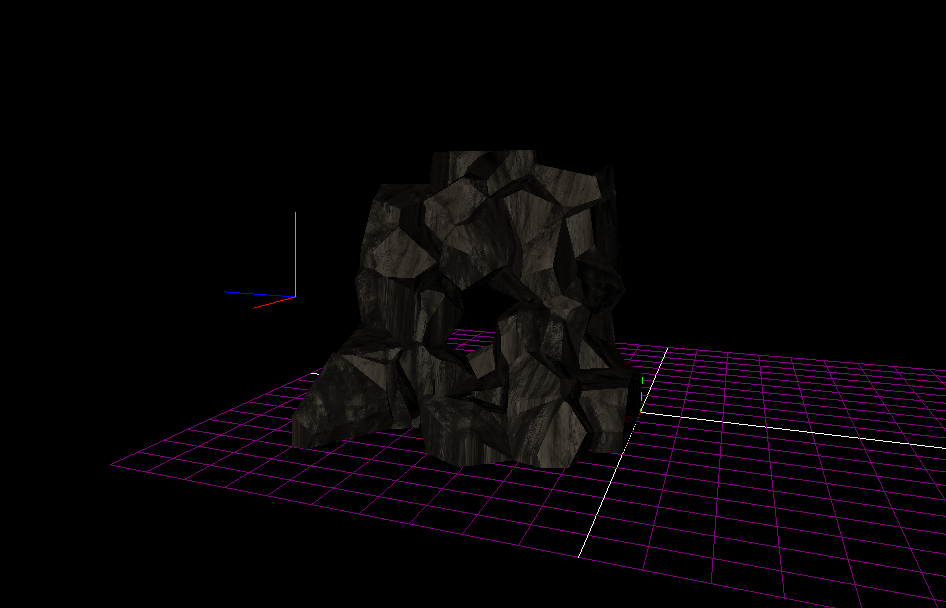
- Creating a voronoi level editor that helps form terain/rock assests. (Example Rock Formation from concept testing bellow)

I Hope this Has been a helpful introduction to Voronoi mathamatics in 3D Space.
Regards - Andrew Watts


Comments